Autopilot installation on 370
 LaRea
Member, Moderator Posts: 7,981 mod
Here's a quick overview of the Raymarine EV-200 autopilot installation on my 2007 Rinker 370. I am a huge fan of autopilot, and I probably use it 80% of the time I'm underway. But most of you already know that, so I'll just focus on the installation.
The system components are:
- Octopus Type R drive with 9-foot cable
- Raymarine M81105 rudder position sensor
- Raymarine ACU-200 autopilot control unit
- Raymarine EV1 heading sensor
- Raymarine R70 control head
First, the actuator. For boats like mine with outdrives and cable steering, the choices are limited. I used an Octopus Type R drive:
http://octopusdrives.com/type-r-drive-family
This drive can be found on eBay for approximately one Boat Unit ($1000). It has two parts: the drive cable and the motor. The drive cable is a 9-foot worm-drive cable that bolts onto the boat's hydraulic-assist steering ram. (There's no need to modify anything at all on the boat's steering system.) The drive motor gets mounted in the engine room and attached to the other end of the drive cable.
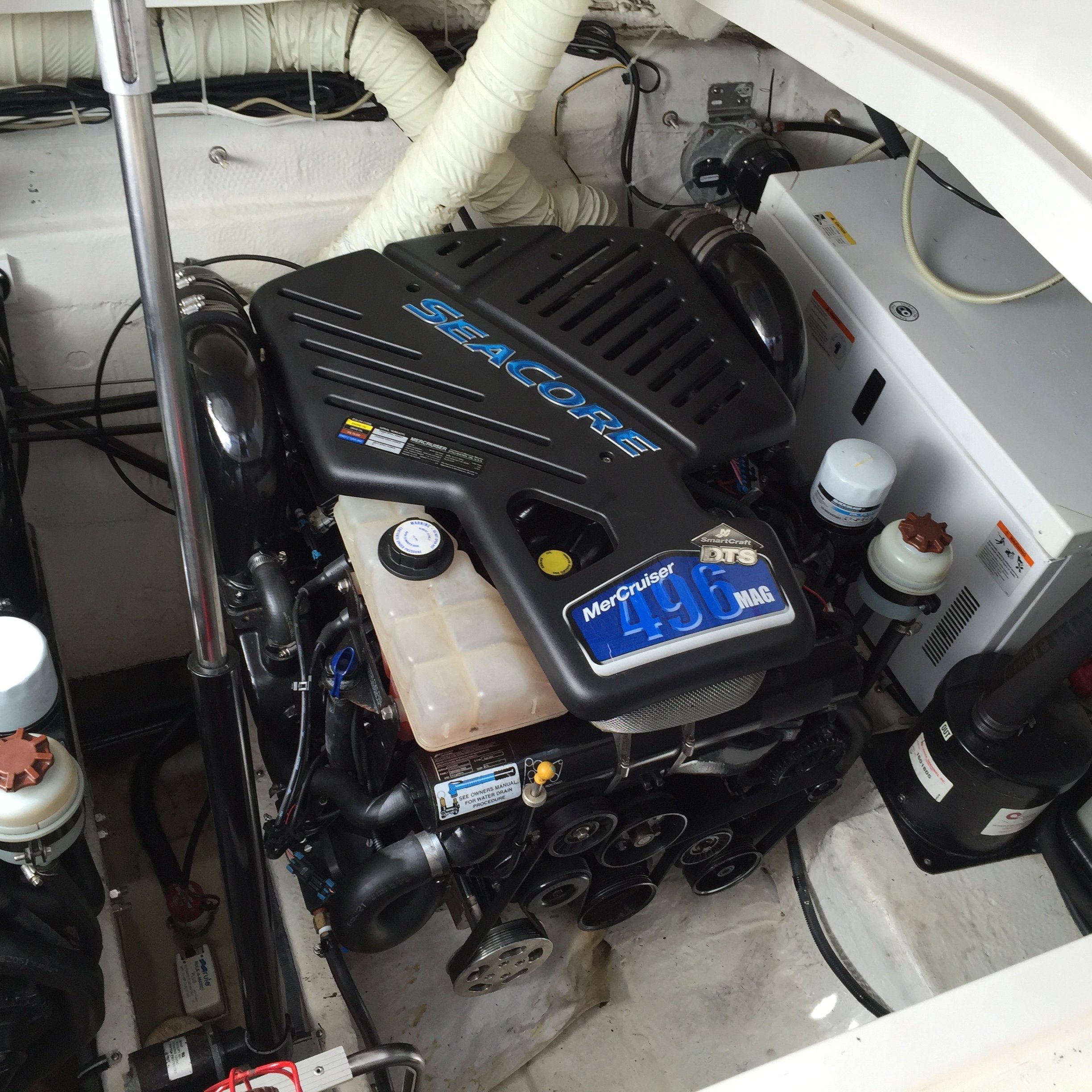
My power steering is on the stbd engine, and I mounted the drive motor on the transom at the port side, aft of the generator. The cable routing is critical, because the cable needs to move freely back and forth as you steer the boat. My cable exits the drive motor on the port side, then makes a 180-degree turn back towards the stbd side. From there, it is routed along the transom to the stbd motor.


This is not a pretty installation. The gear casing of the Octopus drive motor is cast aluminum with no finish whatsoever, so it started corroding before I even took it out of the box. I should have painted it before installing it.


The next component in the chain is the Raymarine rudder position sensor. Actually, when I bought the Octopus drive, I paid extra to get the optional built-in position sensor. (In the photo above, it's the black plastic box with the grey wire.) Unfortunately, the autopilot refused to recognize it, so I ended up using the Raymarine sensor. I mounted it on the transom between the engines, and used hose clamps to attach the sensor arm to the outdrive steering bar.
In the picture below, you can also see the Octopus drive cable running parallel to the steering bar, just below and forward of it.

In the picture below, you can also see the Octopus drive cable running parallel to the steering bar, just below and forward of it.

The controller (ACU-200) is mounted on the forward bulkhead, stbd side. I have a 5-port Seatalk junction box nearby for the ACU-200, GPS and EV1.


For the EV1 sensor, it's important to find a location away from sources of magnetic interference. I mounted mine under the helm seat, and the location has worked well for me. The fiberglass seat support has an access port on the port side -- just a piece of Starboard attached with four screws. I removed the access panel and attached the EV1 on the inside. You can see the three mounting screws poking through the Starboard.


The R70 control head is mounted at the helm. I relocated my bow thruster control and spotlight controller, and put the R70 in that spot. (I also added an i70 to display engine data, but that's not required for the autopilot.)


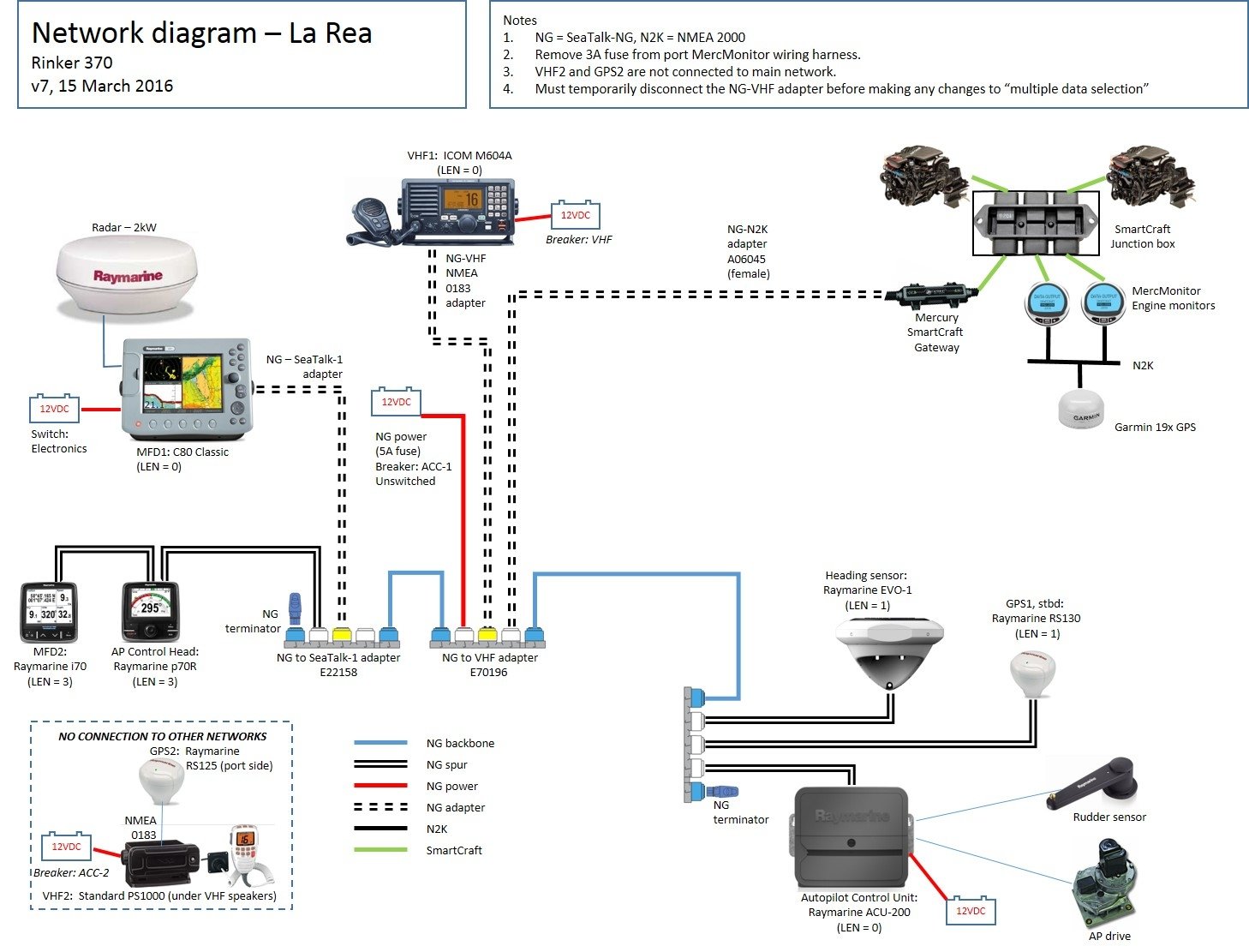
Wiring is relatively simple. There are four wires from the ACU-200 to the Octopus, and two wires for the rudder sensor. The rest is Seatalk NG network cables. Here's a diagram of my system.


I have been really happy with this system. I will admit that it took me a lot of trial and error to install the Octopus drive, so maybe this post will help others who are trying the same thing. The system has been super-reliable and easy to use. By the way, if you've never had a rudder position sensor, it's worth getting one even if you don't have an autopilot. It takes some of the guesswork out of docking.

Comments
It's easier than it looks, and the instructions are good. (Both images below are copyright Octopus Products Inc.)
Dream 'Inn III -- 2008 400 Express
The stbd end of the Octopus drive cable casing is attached to the moving part of the steering ram. That means the last few feet of the the drive cable will move back and forth probably 7-8 inches as you turn the steering wheel.
To allow for this movement, the drive cable must have a "service loop" before the drive motor. That's why my cable comes out pointed to port, then makes a 180 degree turn to stbd.
In the doctored photo below, the red line shows the path of the drive cable. The bottom part of that service loop would actually be sitting on the deck, and the constant back-and-forth motion would eventually cause the casing to chafe. To prevent that, I made a loop from cable ties and hung it over the top part of the drive cable (shown by the yellow line).
The cable ties are a temporary solution. It has worked fine for two years, but obviously I need a more permanent solution there.
The key is to get in the engine room and watch the drive cable while somebody moves the steering back and forth, so you can understand how to keep the cable from chafing.
The cable shouldn't add more than a pound or two of effort (easily overcome by the power steering).
Turns out he had the drive hooked up wrong to the computer.
The computer has 3 termnals for the drive. MOTOR MOTOR COMMON
You want to use the 2 MOTOR terminals.. NOT THE COMMON. Common is left open
This was my wiring. Did I get it wrong?
I would agree that you have it hooked up correctly according to the directions.
@LaRea when you disengage the autopilot while it is turning say to starboard, do you have to turn the wheel slightly more to starboard to release the clutch, or can you immediately turn to port with no issue?